|
|
||
|---|---|---|
| assets | ||
| qmk | ||
| via_keymaps | ||
| README.org | ||
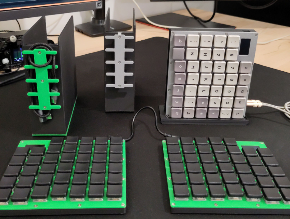
Snappy
Snappy is a custom, QMK-based split keyboard designed for simplicity, with a focus on portability and repairability.
After using multiple different custom keyboards over the span of 2 years I identified the following requirements that I deemed important:
- Spilt keyboard with individually usable halves
-
Reasonable amount of usable keys while maintaining low footprint
- Dedicated number row
- Some function keys
- Extra columns
- No rotation or special placement of thumb keys
- Low profile switches for comfortable usage w/o wrist rests or tilt kit
- Good portability, ideally with a matching carrying case
-
Mostly 3D printable
-
Individual Parts should be replaceable without re-soldering anything
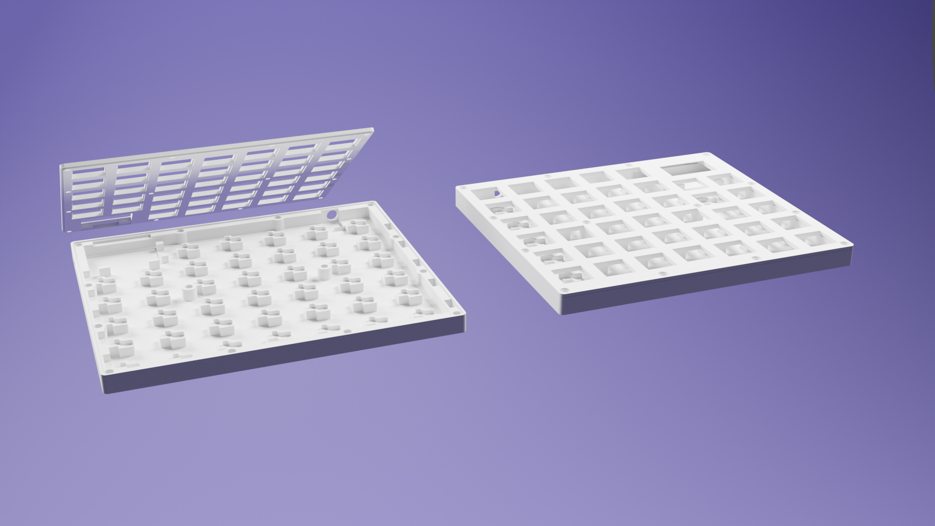
- Top Plate
- Bottom Housing
-
-
Handwired version
- Support vor hotswap sockets !Kailh only!
- OLED display
- PCB version
-
Wireless version
- This version might feature a battery in place of the OLED display
-
Some Accessories
-
Carrying case
- Features a dual function cable holder / connector for halves
- Portable mini tilt kit
- Stationary tilt kit(s)
-
As observable in the list above many of the requirements and ideas have already been implemented during the last three iterations of Snappy. The remaining ideas will be implemented in no particular order or timeline.
Bill of Materials
Snappy BOM (English)
TODO: BOM in English
Snappy BOM (German)
Grundsätzlich ist es empfohlen für die Handwired version mit Hotswap Sockets Kailh V1 Switches zu verwenden. Wir haben jedoch auch schon eine Snappy mit Kailh V2 Switches gebaut was auch funktioniert hat, jedoch aufgrund der minimal größeren Switches, vor allem der größere Durchmesser des "Center Mast" führt zu etwas Spannung der "Top Plate" und bedarf etwas mehr Vorsicht beim späteren zusammenführen der gelöteten matrix aus Hotswap Sockets und "Bottom Housing". Mit etwas Geduld und Gefühl klappt das dann aber auch.
Bei allen Bauteilen die man löten muss, gerade als Anfänger, lieber ein paar mehr besorgen. Je nachdem ob ich das Filament schon in der Farbe habe oder nicht kann man den Preis vom Filament für die gesamte Tastatur + Case + Tiltkit auf ca 10 € runter schrauben.
Snappy v3 Tastatur (mit Hotswap):
-
80x Kailh V1 (Choc) kompatible Keycaps (ca. 50 € - 100 €, je nach KC & Angebot)
- Work Louder
- MBK Legend
- MBK PBT Coloured Blank Keycaps (Homekeys nicht vergessen)
-
80x ACHTUNG -> MX/Kailh V2 kompatible Keycaps (ca. 50 € - 100 €, je nach KC & Angebot)
-
80x Kailh V1 Keyswitch (ca. 40 € - 85 €, je nach Switch & Angebot)
-
2x RP2040 Pro Micro 16M (ca. 8 €) || 2x Liatris (ca. 35 €) || 2x 0xCB Helios (ca. 32 €)
-
80x Hotswap Socket für Kailh V1/V2 Switches (ca. 10 €)
-
80x 1N 4148 Schalt-Diode, 100 V, 150 mA, DO-35 (ca. 1 €)
-
2x OLED Display 128x64 (i2c -> GND,VCC,SCK,SDA) (ca. 3 €)
-
2x TRRS Jack (ca. 1 €)
-
1x 30cm - 60cm TRRS Kabel (Am besten 90deg Winkel) (ca. 2 €)
- Beispielhaftes Produkt
-
- In die Notiz vor dem Kauf schreiben: 90 TRRS to 90 TRRS, straight type, 30CM, Inner Color: 32 (Black) + Outer Color: Red, Black heatshrink.
-
ca. 400cm, Kupferlackdraht Ø 0,30mm - 0,40mm (ca. 3 €)
-
28x Heat Insert M2(OD3.2mm, H3mm oder 4mm) (ca. 2 €)
-
28x M2 Schraube H6mm (ca. 1 €)
-
10x 7mm x 3mm Neodym Magnet (ca. 1 € - 10 €)
- Beispielhaftes Produkt (Sehr gute Qualität, Haltkraft und schnelle Lieferung)
-
8x 8mm x 2mm Gummi Füße (ca. 1 €)
-
1x 0,5m USB-C Kabel (ca. 5 €)
-
3D Druck Filament in Farbe eurer Wahl (PLA, PET-G) (ca. 10 € - 30 €, je nach Farbe, etc.)
- Für Mehrfarbige Prints dann natürlich mehrere Farben
Günstig (MC, KS, KC): ca. 98 € Teuer (MC, KS, KC): ca. 215 € Restliche Kleinteile: 50 € Gesamt: ca. 150 € - 270 € (+- 20€, je nach aktueller Preislage)
Carry Case + Snappy Connector/Cable Organizer:
-
14x 7mm x 3mm Neodym Magnet (ca. 1 € - 10 €)
- 10x Case + 4x Snappy Connector
- Beispielhaftes Produkt (Sehr gute Qualität, Haltkraft und schnelle Lieferung)
-
9x Heat Insert M2(OD3.2mm, H3mm) (ca. 2 €)
-
6x M2 Schraube H6mm (ca. 1 €)
-
3x M2 Schraube H12mm (ca. 1 €)
-
3D Druck Filament in Farbe eurer Wahl (PLA, PET-G) (ca. 10 € - 30 €, je nach Farbe, etc.)
- Für Mehrfarbige Prints dann natürlich mehrere Farben
Gesamt: ca. 10 €
Other Accessories (Tilt Kits, Show Stand, etc.) JEWEILS:
-
10x 7mm x 3mm Neodym Magnet (ca. 1 € - 10 €)
- Beispielhaftes Produkt (Sehr gute Qualität, Haltkraft und schnelle Lieferung)
-
3-6x M2 Schraube H6mm (ca. 1 €)
-
3-6x Heat Insert M2(OD3.2mm, H3mm) (ca. 2 €)
-
3D Druck Filament in Farbe eurer Wahl (PLA, PET-G) (ca. 10 € - 30 €, je nach Farbe, etc.)
- Für Mehrfarbige Prints dann natürlich mehrere Farben
Gesamt: jeweils ca. 10 €
Build Instructions
Required Tools
Hardware:
- Tweezers
- Wire cutter
- Soldering iron
- Solder
- Fume extractor
- Usb-C cable: for testing & transfer of the firmware
- Skrewdriver suitable for the selected skrews
Software:
-
Clone of the QMK Repository
Check Bill of Materials (Keyboard)
Check if you have all required parts from the BOM.
Snappy v3 Tastatur (with Hotswap):
- 80x Kailh V1 (Choc) compatible keycaps
- 80x Kailh V1 keyswitch
- 2x RP2040 Pro Micro 16M || 2x Liatris || 2x 0xCB Helios - microcontroller
- 80x Hotswap socket for Kailh V1/V2 switches
- 80x 1N 4148 diodes, 100 V, 150 mA, DO-35
- 2x OLED display 128x64 (i2c -> GND,VCC,SCK,SDA)
- 2x TRRS jack
- 1x 30mm - 60mm TRRS cable
- 28x Heat insert M2 (OD3.2mm, H3mm oder 4mm)
- 28x M2 skrews H6mm
- 10x 7mm x 3mm neodym magnets
- 8x 8mm x 2mm rubber feet
- 14x 40cm, enameled wire Ø 0,30mm - 0,40mm
- 8x 20cm, enameled wire Ø 0,30mm - 0,40mm
- 12x 15cm, enameled wire Ø 0,30mm - 0,40mm
- 8x 10cm, enameled wire Ø 0,30mm - 0,40mm
Ensure Microcontroller Functionality
-
Flash the snappy v3_5 QMK firmware onto both microcontrollers (MCs)
- Check with
lsusbif there is a devicecafe:1337 phga snappy v3.5 - Take some tweezers or a wire and try to activate some keys
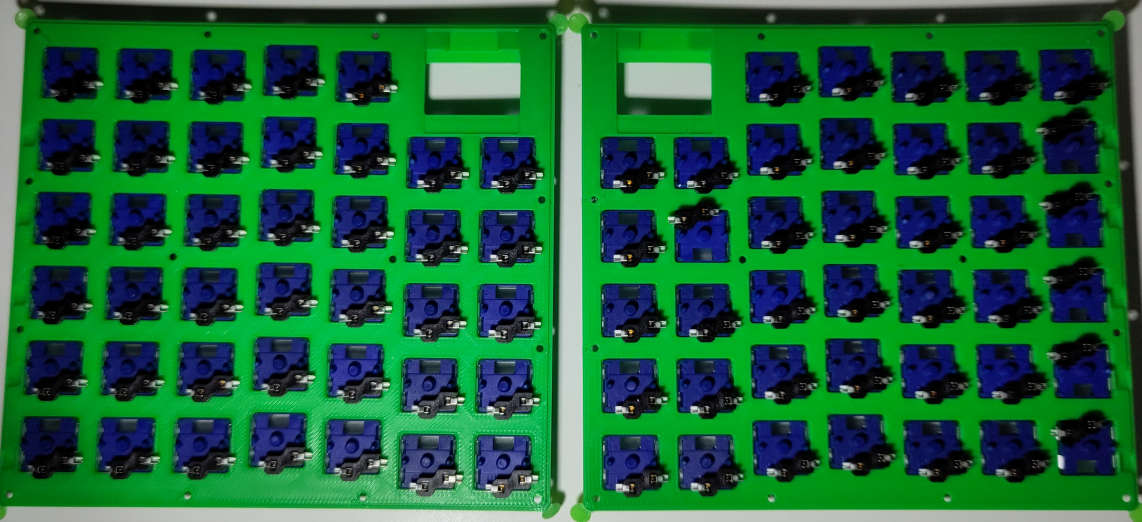
Prepare Both Bottom Halves
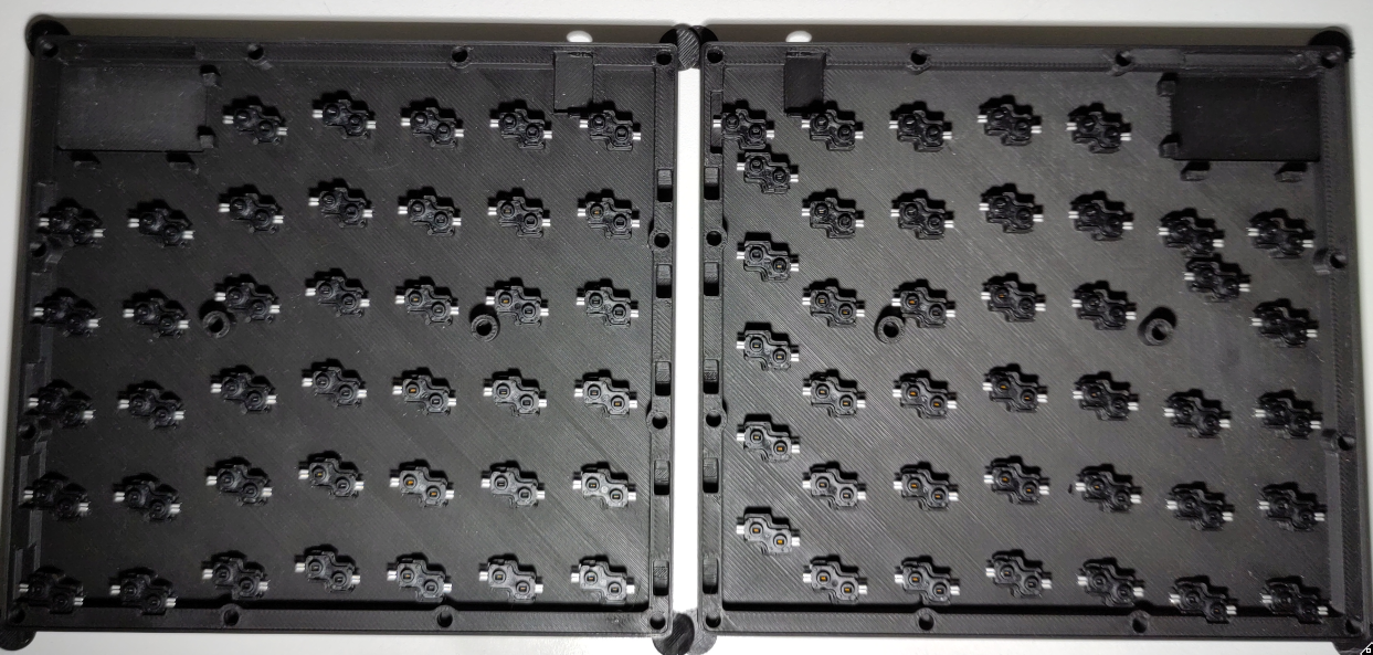
-
Insert all hotswap sockets into the holders of the two bottom halves.
- There IS a correct orientation (you can't insert them otherwise)
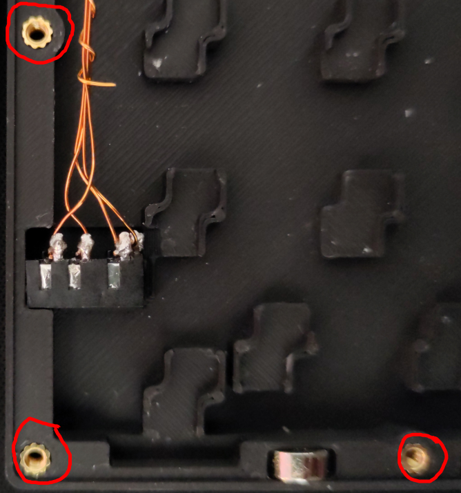
-
Also insert the heat inserts into both bottom halves
- Make sure to insert them with the soldering iron set to 250°C
- Try to insert them as straight as possible
Prepare Both Top Halves
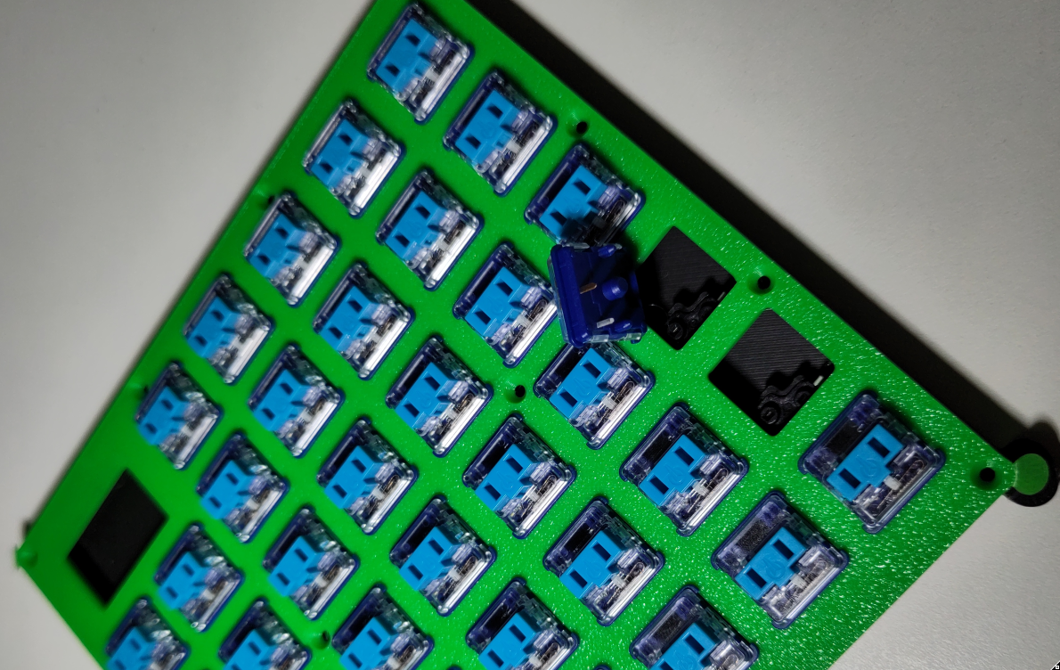
- Place the top plates onto the bottom halves with the hotswap sockets
-
Insert all keyswitches through the top plate into the hotswap sockets
- Be mindful because the pins on the keyswitch easily bend
- The silver pin usually is a bit more rigid than the bronze one (try using the silver one as a guide)
Get Ready to Solder
-
Remove the top halves from the bottom halves
- The hotswap sockets should stay attached to the keyswitches & thus the top halves
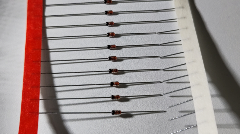
- Prepare your diodes by shortening the side WITHOUT the black (anode) mark as seen in the picture
-
The goal is to shorten the anode of the diodes not too much
- Later we want to be able to archive similar results as shown in the following picture
General Notes on Soldering
-
Standard range: 315-380°C for hand soldering
- Enameled wire: 370-400°C (to burn through the enamel coating)
- Lead-free solder: Requires higher temperatures around 260°C
- Contact time: 2-5s, adjust as needed
- Cold/Bad Joints: Dull, whitish, frosted appearance
- Good Joints: Shiny, smooth finish
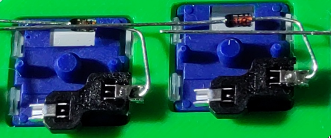
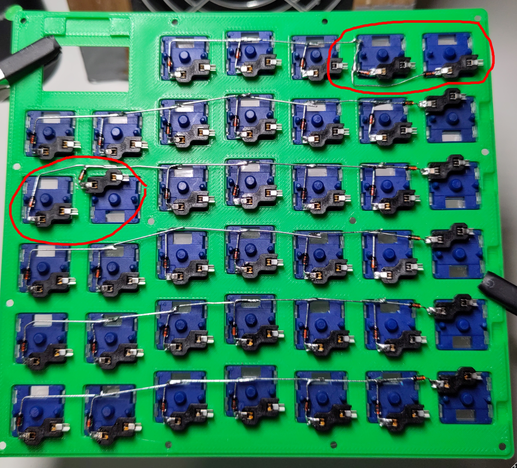
Soldering the Rows
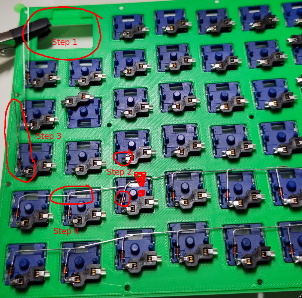
-
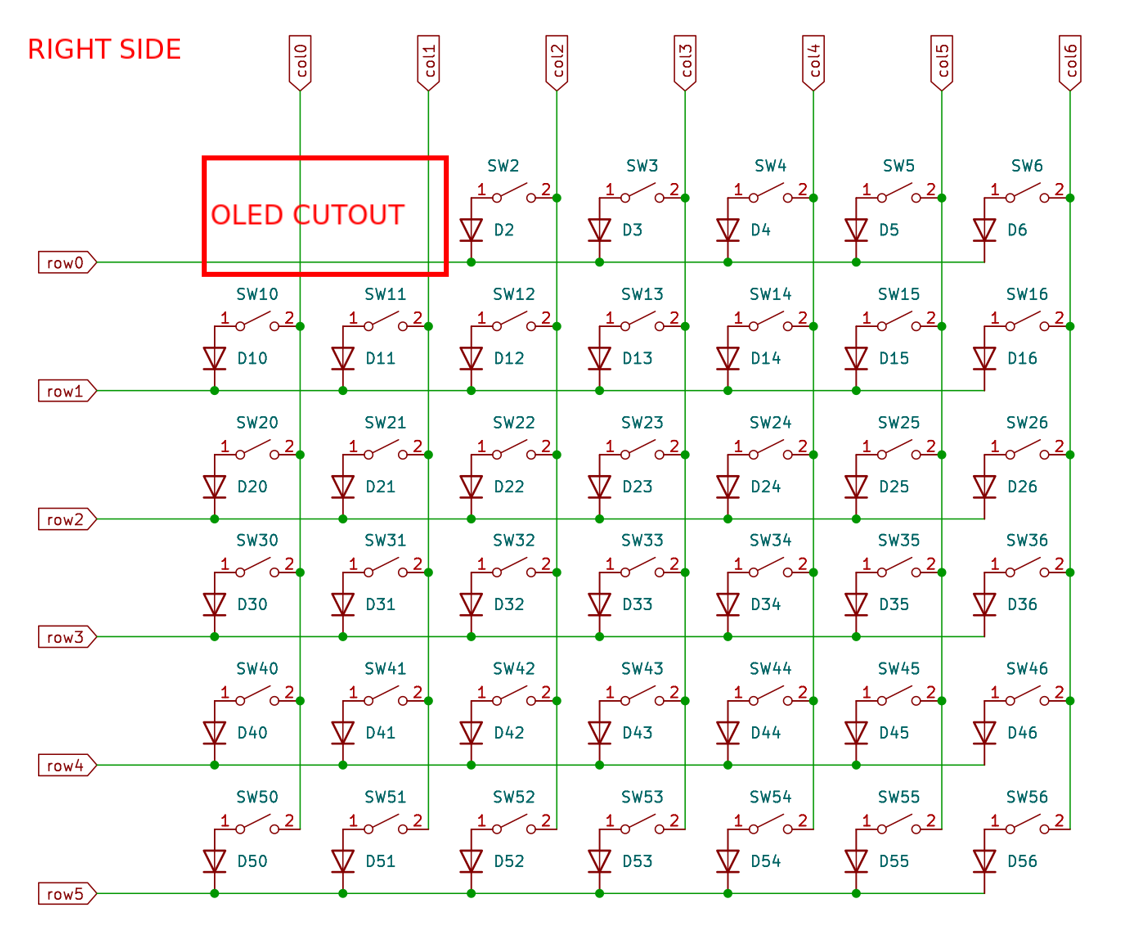
Identify which half you are soldering right now
- If the OLED-cutout is on the left, you are soldering the right side & vise versa
- The cutout for the the OLED-display marks the column to start with
- Put a bit of solder onto the connector of the hotswap socket that is on the same side as the OLED-cutout of this half (when looking at it from the top)
- Reheat the solder and insert the shorter lead without the black stripe (anode) into the connector of the hotswap socket
- Bend the longer leads, as shown in the picture, to form a connected line from the first column (OLED-cutout) to the last column
-
Solder the overlapping leads to establish electrical connectivity
- Cut off excess leads
TAKE NOTE BEFORE SOLDERING ANYTHING ON BOTH HALVES

-
Right side (OLED-cutout on the left, from your current back-to-front view)
- The last two hotswap sockets in the first row MUST be connected like this to leave enough space for the TRRS jack
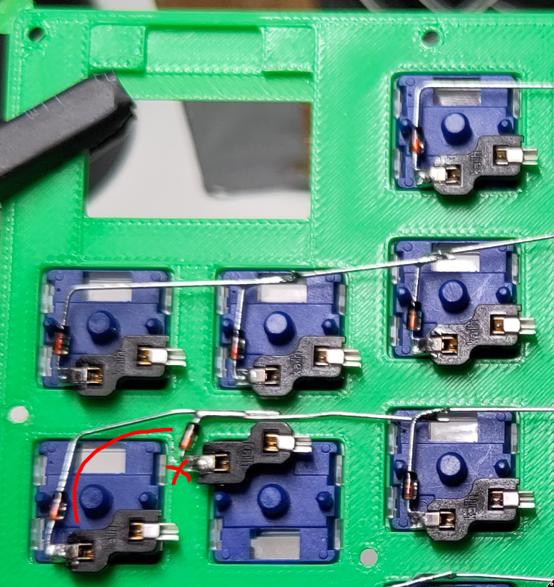
-
Right side (OLED-cutout on the left)
- The first two hotswap sockets in the third row MUST be connected like this to leave enough space for a skrew that holds the top plate
-
Left side (OLED-cutout on the right)
- The last two hotswap sockets in the first row MUST be connected like this to leave enough space for the TRRS jack
⟲ Repeat the same steps for the other side
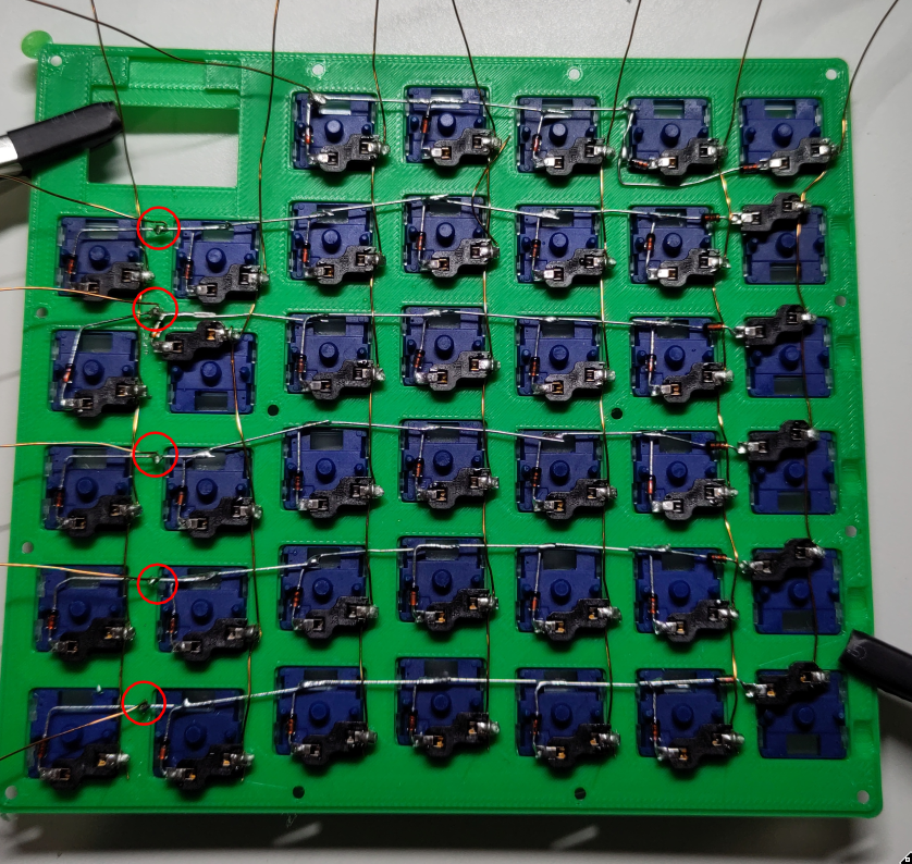
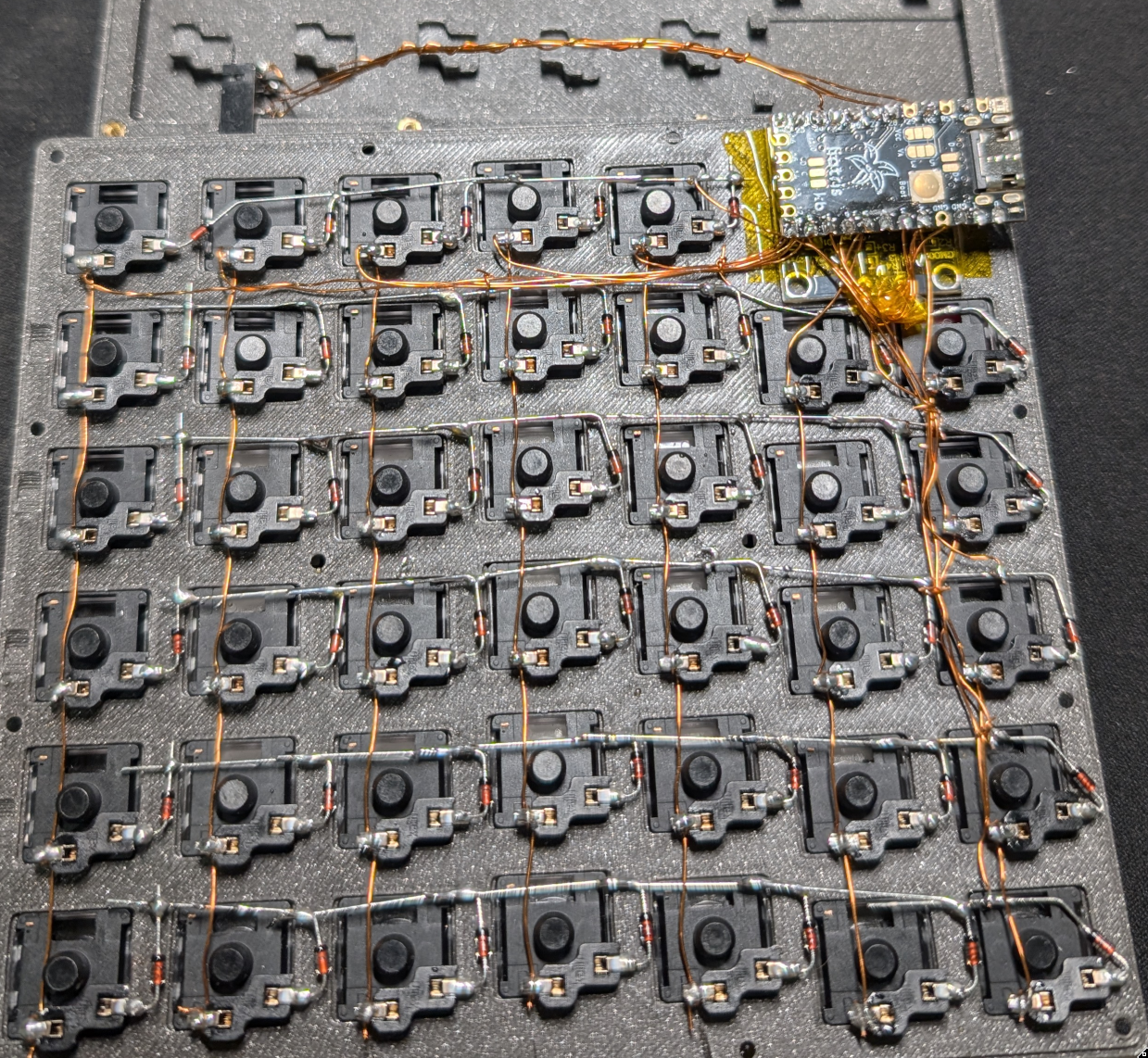
After this stage, both sides should look something like this picture of the right side
- The left side only has the one special joint in the top left corner (TRRS Jack)
- The right side with two special joints is shown in the following picture
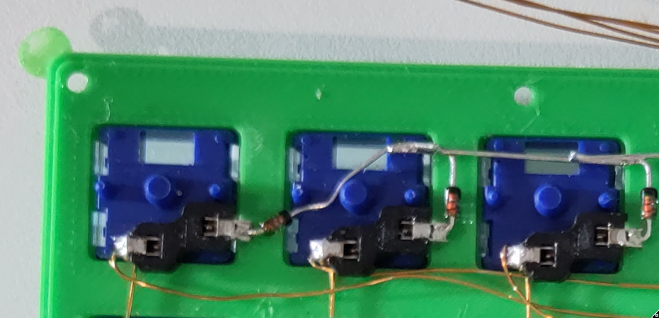
Soldering the Columns
You'll need the 40cm enameled wire pieces for this step
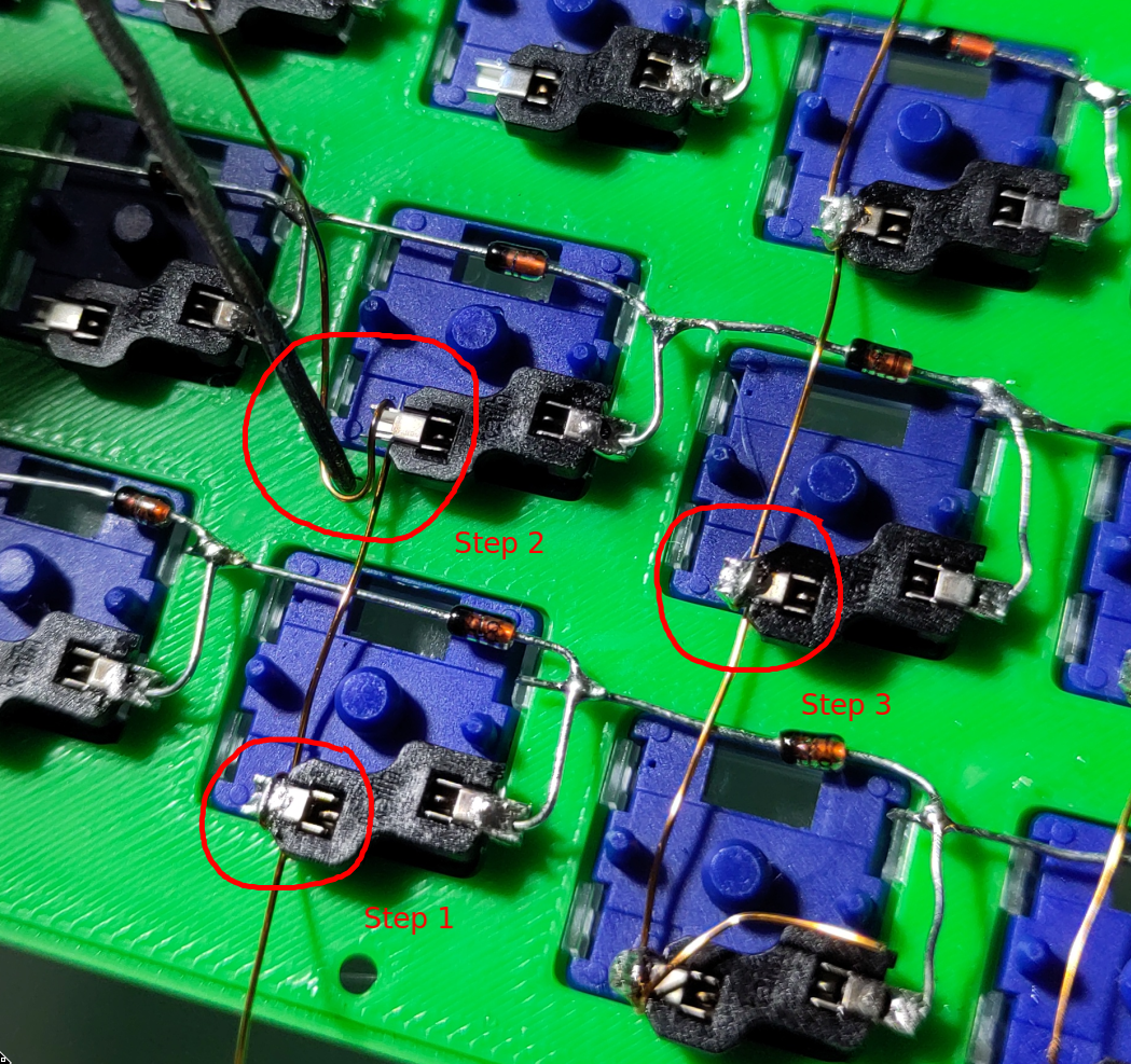
- Wrap one end of the enameled wire around the bottom most hotswap socket of a column and establish a solder joint to hold it in place
- Use a pair of tweezers or something pointy to wrap the wire around every hotswap socket in this column
-
Establish a solder joint on every hotswap socket / wire connection in this column
- NOTE: Starting with the top most connection secures the wire in place
⟲ Repeat the same steps for every column on both halves
- Make sure that the rest of the wire from each column is long enough to reach the OLED-cutout with some extra wire left
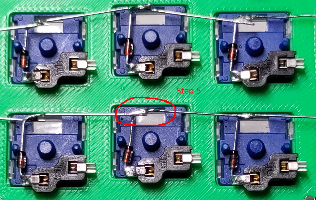
Extending the Rows
You'll need the 15cm enameled wire pieces for this step
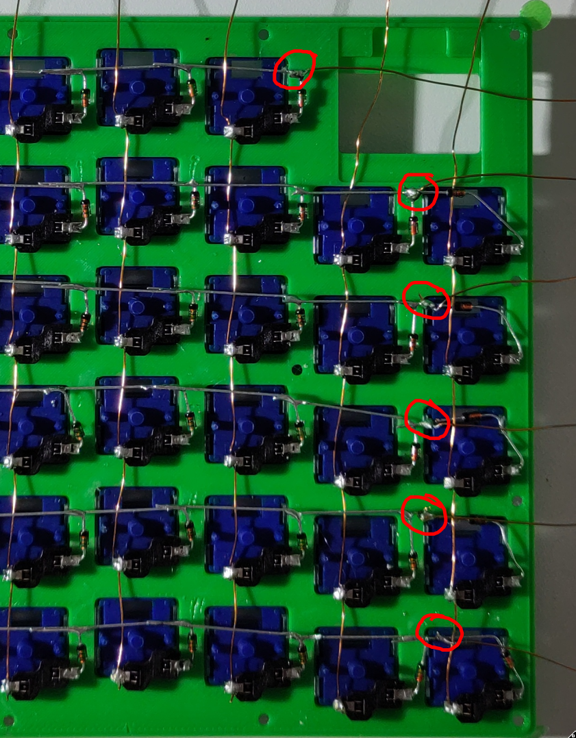
-
For each row: solder one end of a wire to the intersection point of the diodes next to the first column (the one underneath the OLED-cutout)
- Make sure to solder on the cathode side (with black mark) of the first diode
- Make sure that you do not destroy the connection of the row itself
- It is easier to first wrap the wire around the intersection and then solder
⟲ Repeat the same steps for the other side
After this stage, both sides should look something like this picture of the right side
Prepare & Solder the Rest of the Components
You'll need the 10cm & 20cm enameled wire pieces for this step
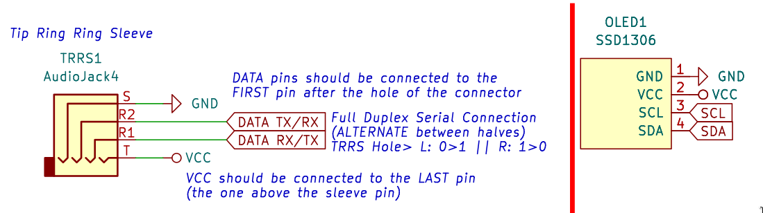
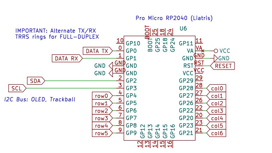
The following diagrams are from the schematics pdf and should be used as a reference during the rest of the soldering.
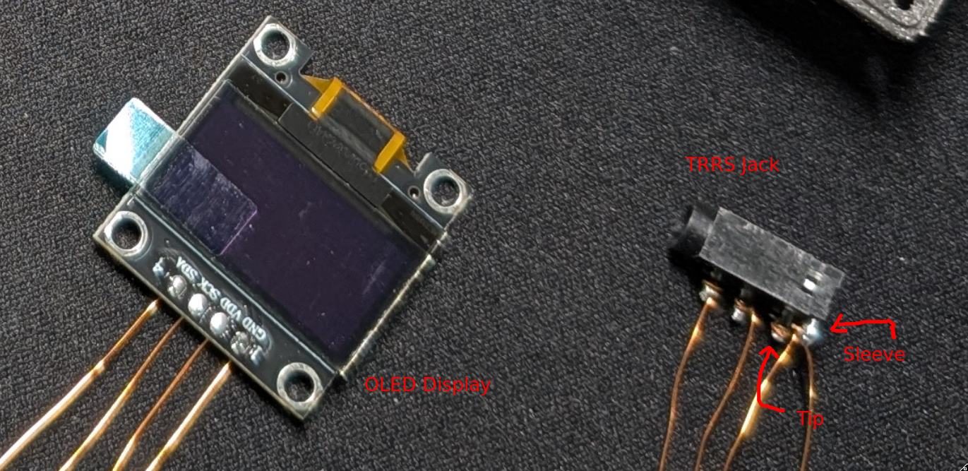
- Solder the ends of the 8x 10cm wire pieces to the OLED displays
-
Solder the ends of the 8x 20cm wire pieces to the TRRS jacks
- VCC is the last pin (furthest away from the hole) in the row of three pins
- GND (Sleeve) is the single pin that is on the other side of the three pins
- DATA TX/RX are the first two pins after the hole in the row of three pins
- Make sure to ask if anything during this phase is not described clearly enough or if you are unsure what to do
-
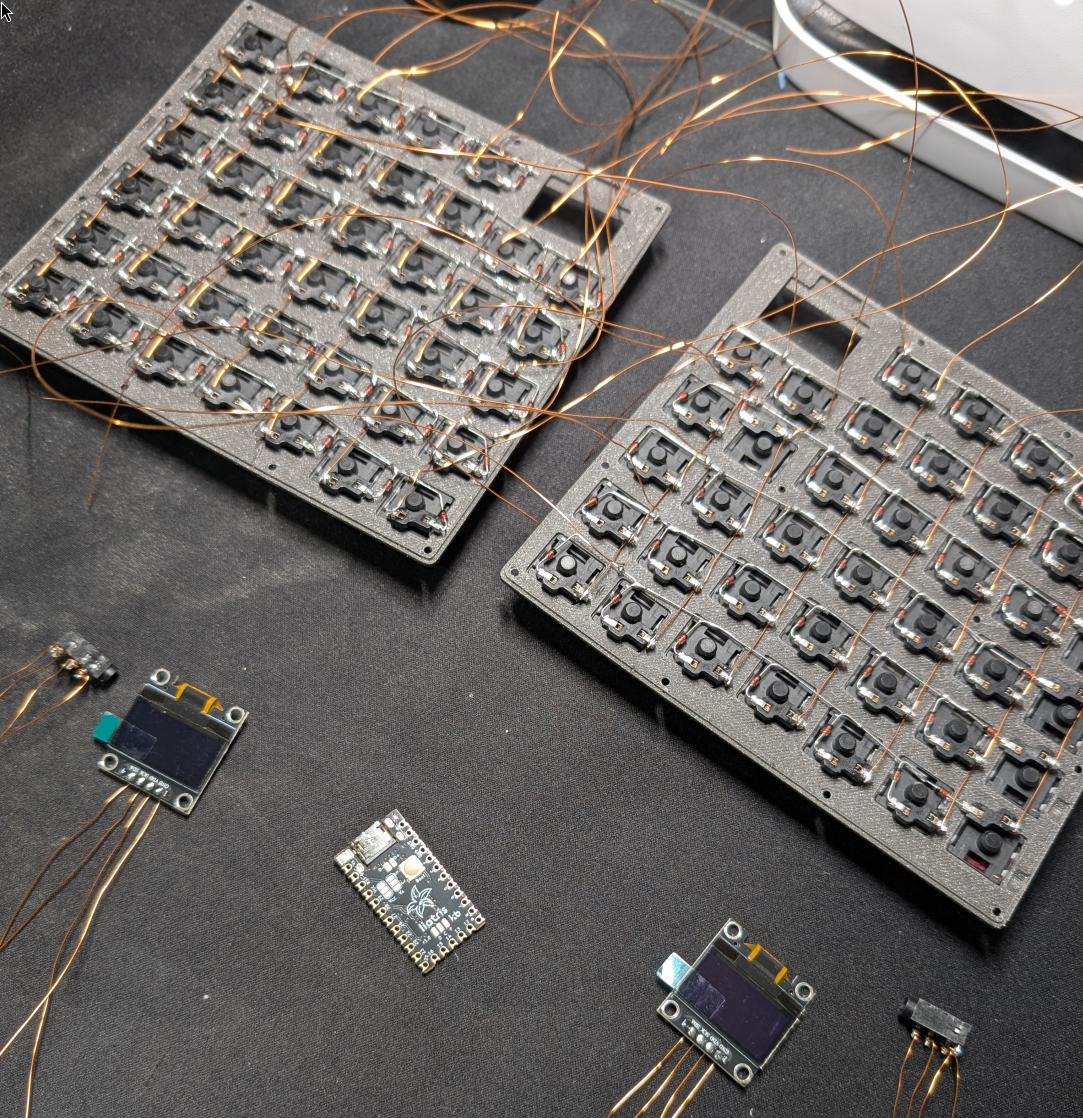
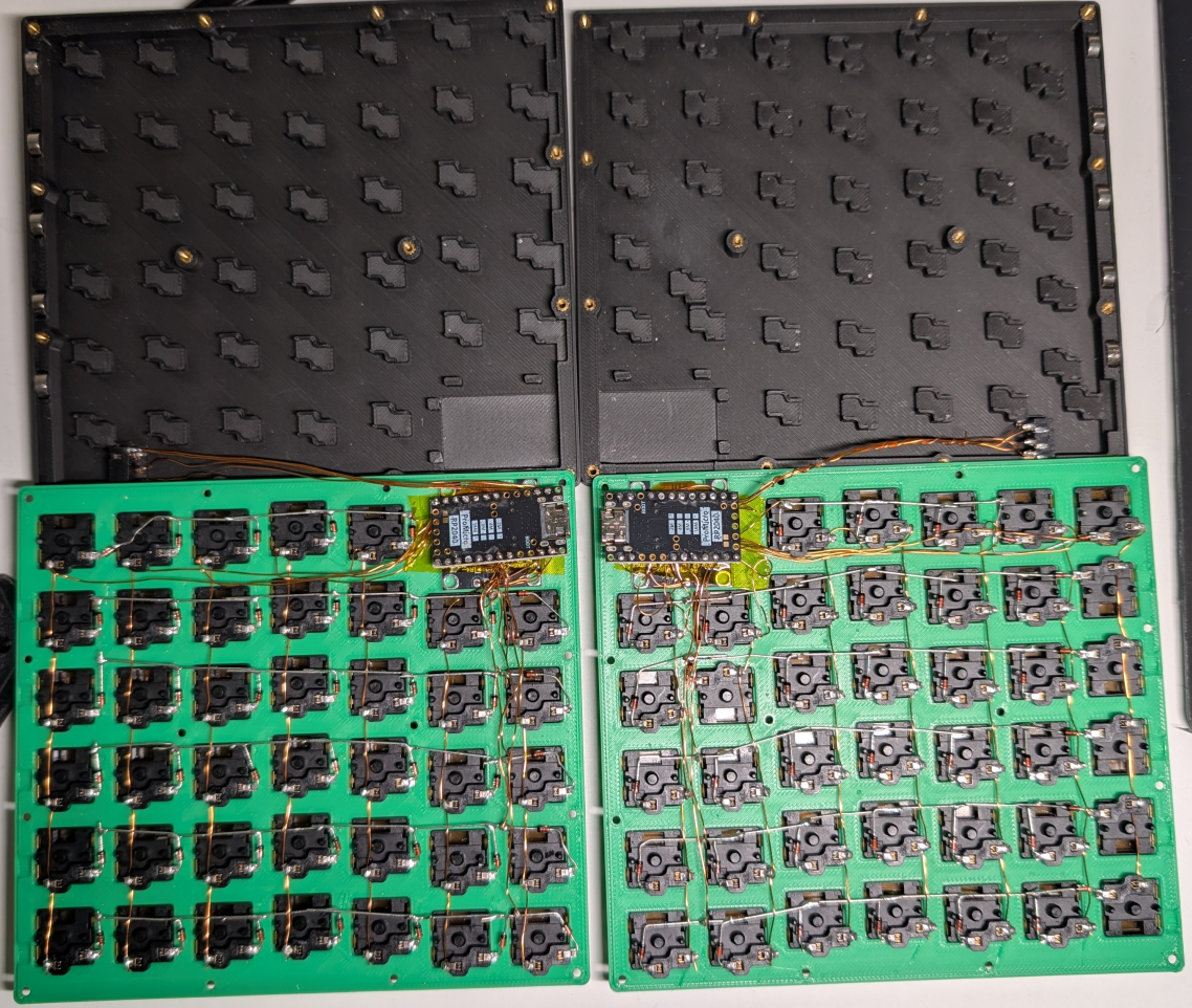
Place your microcontroller on top of the OLED-cutout
- Make sure that the controller is oriented correctly (look at the following pictures)
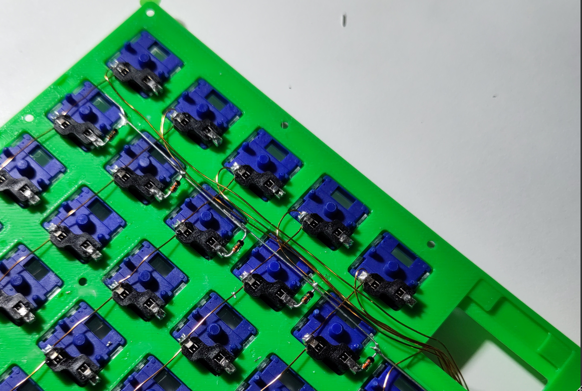
COLUMNS
- Neatly route your column cables in between row0 and row1 to the microcontroller
-
Carefully insert each column wire into the respective pin on the microcontroller (see diagram & next pictures)
- Insert the cables from below. The cables must later be in between the OLED display and the microcontroller
- Make sure that the controller is positioned with some "slack" of the wires in mind (not too much slack though; this part is crucial and somewhat fiddly; re-adjust after every newly inserted wire)
ROWS
- Neatly route your row cables in between col0 and col1 to the microcontroller
-
Carefully insert each row wire into the respective pin on the micro controller (see diagram & next pictures)
- Insert the cables from below. The cables must later be in between the OLED display and the microcontroller
- Make sure that the controller is positioned with some "slack" of the wires in mind (not too much slack though; this part is crucial and somewhat fiddly; re-adjust after every newly inserted wire)
TRRS JACKS
- Neatly route the 4 wires of each TRRS Jack to the microcontroller
-
Carefully insert each TRRS jack wire into the respective pin on the micro controller (see diagram & next pictures)
- Insert the cables from below. The cables must later be in between the OLED display and the microcontroller
-
When inserting the TRRS jack wires into to the microcontroller make sure to alternate the R1/R2 pins for the left & right side.
- Snappy uses a full duplex connection between both halves
-
To be compatible with other Snappy halves, use the same wiring as shown in the diagram
- Left: Hole > GP0 > GP1 > VCC > GND (sleeve)
- Right: Hole > GP1 > GP0 > VCC > GND (sleeve)
OLED DISPLAY
-
Place the OLED display into the slot underneath the microcontroller and route the wires into the microcontroller (see diagram & next pictures)
- Insert the cables from below. The cables must later be in between the OLED display and the microcontroller
- Place some strips of capton tape over the OLED display to protect it from shorts with the microcontroller (This could be enhanced in future versions but space is very limited)
For the last time make sure that the microcontroller is in the right spot (see picture below as a reference)
- Notice how it is a bit outside to the right there: This ensures, that the USB port fits neatly into the cutout in the bottom shell
-
Dry fit the top half to the bottom half to see if the cable routing/length is sufficient
- Cables sholud not be too long but also not too short
- The microcontroller should snap into its place and the USB-C connector should fit into its cutout
Start to solder all wires to the micro controller
- When in doubt, ask for help when soldering the MC, if the MC is fried, we cant reverse it
-
Make sure to place the tip of the soldering iron:
- on the metal of the microcontroller pin
- touch the wire at the same time
- add some solder to help distribute the heat to the wire so that its coating can burn easier
Putting it All Together
MAGNETS
-
Ask for the correct orientation of the magnets
- Only necessary if you want to be compatible with others
- Insert the magnets into the slots of one bottom half
- Secure the top half onto the bottom half so that the magnets are seated securely
-
Take a stack of magnets and test the correct orientation for the other half by attaching the stack to the first half
- Take note of the correct orientation
⟲ Repeat the same steps for the other half & make sure your halves are attracted to each other
TEST FUNCTIONALITY
- Connect both halves with your TRRS cable
- Plug any half into a computer
- Check if the other half is also powered and if both halves send keycodes to your computer
SKREWS
- When both halves work as expected put in the rest of the skrews
If you did everything correctly, you should now have a "working" Snappy (:

How to Flash the Firmware
Required repositories
- https://g.phga.de/phga/snappy-public (keymaps & general definitions for Snappy)
- https://github.com/qmk/qmk_firmware (firmware base)
Documentation for all available keycodes of the firmware
How to Flash the Firmware
If you want a more "user-friendly" experience: Flash via Via (Use Via)
The process is also partially documented in snappy-public/qmk/snappy/README.md
Since Snappy has yet to be released to the official QMK repo–for now–additional steps are necessary.
- Copy the folder
snappy-public/qmk/snappy(snappy-public) toqmk_firmware/keyboards/snappy(the qmk project – firmware) -
Keep the "innermost" key pressed, while plugging in the half you want to flash
- Innermost means the key in the first row (the one with the OLED display) that is furthest from the OLED display.
- NOTE: Both halves SHOULD be flashed with the same version of the firmware
- Mount the blockdevice (
lsblk) of therp2040to/media/snappy(this allows for automatic upload of the img) -
Either choose an existing layout or create your own by e.g. copying the an existing one
cp snappy-public/qmk/snappy/rev3_5/keymaps/qwertz snappy-public/qmk/snappy/rev3_5/keymaps/my_cool_layout- The folder name is than used in the
makecommand for flashing to select the layout - You can adjust the
keymap.cfile as needed (either check out the code or use the qmk documentation) - For
QWERZusers, check section OS Layouts: Note on QWERTZ
- Navigate in the root directory of the
qmk_firmwarefolder and run the following commands
# REV3_5 (promicro rp2040)
# RIGHT Half
sudo make snappy/rev3_5:$MY_LAYOUT_FOLDER_NAME:uf2-split-right
# LEFT Half
sudo make snappy/rev3_5:$MY_LAYOUT_FOLDER_NAME:uf2-split-left

# OTHER Layouts (example with QWERTZ layout REV3_5)
sudo make snappy/rev3_5:qwertz:uf2-split-right
sudo make snappy/rev3_5:qwertz:uf2-split-left

# Make sure to mount the RP2040 drive to /media/snappy for automatic copying of the .uf2 file
NOTE: After the flash was successful, the rp2040 automatically reboots with the new firmware
Flash via Via (Use Via)
Navigate to using a Chrome based browser (firefox might not work):
- https://usevia.app/
- Settings > Show Design tab
-
Design Tab > Load Draft Definition
-
On GNU/Linux:
- Navigate to
chrome://device-logfind hidrawXYZ (or allowrwfor any hidraw device) sudo chown $USER /dev/hidrawXYZ
- Navigate to
- Configure > [Authorize device +]
- Start configuring
NOTE: For QWERZ users, check section OS Layouts: Note on QWERTZ
OS Layouts: Note on QWERTZ
Keycodes in QMK are aliased with QWERTY keycodes. Thus, if you are using a QWERTZ layout
on your device you have to mentally translate the QWERTY keycodes to the related QWERTZ
outputs of your OS-Layout when configuring your keyboard.
EXAMPLE: The keycode KC_Z / Z will output a Y while using QWERTZ as your OS-Layout.
To easily find all the keys you need, consult the internet, a LLM or use a QWERTZ keyboard
and set your OS-Layout to QWERTY and type all the umlauts/etc. you need and take note
which character appears (aka. reverse mapping)
Table of Most Common Keys
| QWERTY | QWERTZ |
|---|---|
| z | y |
| y | z |
| - | ß |
| ; | ö |
| ' | ä |
| [ | ü |
| @ (shift+2) | " |
| ??? | @ (ralt+q) |
Additional Resources
-
For another visualization of the liatris pins see:
-
All QMK keycodes: